THE USE OF ADAPTIVE ARRAYS FOR WIRELESS BASE STATION
Hung Nguyen
Mountain Technology Inc.
3765 Alcantara Ave.
Miami, FL 33178
Phone: 305-436-8545
Fax: 305-436-8546
E-mail: [email protected]
Abstract
Because spectrum represents a significant capital investment, wireless providers must optimize the return on their investment by increasing the capacity of cellular systems. Maximizing capacity is essential for current cellular providers to compete against new low-cost PCS systems. To be competitive with cellular service providers, new PCS service providers need to increase cell size to reduce capital costs. Adaptive arrays represent the key technology for overcoming the problems faced by both cellular and PCS service providers. This paper presents a survey of current techniques and development in the areas of adaptive arrays for wireless applications. Three areas of importance in using adaptive antennas for base station uplink and downlink usage are the base station antenna array, the adaptive algorithms for interference and multipath mitigation, and the hardware architecture that supports the processing requirements.
Introduction
The use of adaptive arrays or smart antenna for cellular base station application has recently become an active area of research and development. One of the primary reasons for this trend is the fast growing demand for wireless mobile communications. It is estimated [1] that by the end of 1995, there were nearly 30 million U.S. cellular telephone users, and in the first few decades of the 21st century, there will be an equal number of wireless and conventional wireline users throughout the world. In some developing countries, the proliferation of wireless communications is even more dramatic due to the economic and technical difficulty of improving the wireline infrastructure.
There are currently two analog cellular standards, AMPS and NAMPS that use FDMA (Frequency Division Multiple Access), and three competing digital cellular standards, IS-54, GSM and IS-95. IS-54 and GSM both use a combination of FDMA and TDMA (Time Division Multiple Access), and IS-95 uses CDMA (Code Division Multiple Access) which is derived from spread spectrum communications.
There is a consensus in the wireless communication industry [2] that the use of adaptive array processing technique is necessary for capacity enhancement and range improvement. Because the allocated frequency spectrum represents a significant capital investment, increasing the capacity of the cellular system will optimize the return on investment. For large cells such as those in rural areas, the use of adaptive arrays can be effective in range improvement over a larger geographical area and result in lower equipment costs. However, when an adaptive array is used at the cellular base station, several technical difficulties described below, such as co-channel interference, multipath and Doppler spread, must be overcome.
The single channel approach to spectrum efficiency includes the reuse of frequencies in FDMA, the use of time slots in TDMA or the more recent direct sequence spread spectrum technique in CDMA. These all use the same set of frequencies, thus causing co-channel interference from a nearby cell which cannot be reduced by increasing transmitted power [1]. Another type of cellular system-generated interference is adjacent channel interference caused by imperfect receiver filters which allow nearby frequencies to leak into the passband, or from out-of-band interference caused by overloading of front-end subscriber equipment or intermittent inter-modulation products. For voice channels, interference causes cross talk where the users hear interference in the background due to an undesired transmission. For control channels, interference causes missed and blocked calls due to erroneous signaling.
The presence of reflecting objects and scattering in the RF propagation path results in multiple copies of the transmitted signal arriving at the antenna shifted in time and spatial orientation [1]. The random phases and amplitudes of the multipath components cause fluctuation of signal strength or small-scale fading. In addition, the speed of the mobile unit relative to the base station results in random frequency modulation due to different Doppler shift on each of the multipath components.
The use of adaptive arrays for cellular base station antennas may not be suitable when array calibration is a requirement for array processing techniques operations such as superresolution direction finding or constrained beamforming. Array calibration is an expensive process that includes not only the characterization of the array manifold itself, but also the front-end receiving electronics. Temperature and equipment aging may also require periodic re-calibration, which can be a very costly item in the operation and maintenance budget.
What is needed is a low-cost base station antenna array that is built upon existing commercial base station antennas. The array signal processing algorithms should be robust to multipath and co-channel interference, possess low computational complexity, and should not have to depend on accurate calibration or array geometry information.
Background
Antenna arrays are widely used in several areas such as
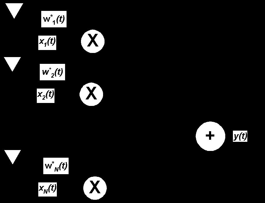
In all beamforming algorithms, the data is taken from an array of sensors, multiplied by a complex weight and summed as shown in Figure 1 below. The weights are designed according to an optimality criterion which will be described below. Each channel of the sensor array would typically consist of an antenna for RF signal (a geophone for acoustic signals), followed by a receiver. For a digital beamformer, the data from each receiver is digitized and fed into a set of Digital Signal Processor (DSP) cards for data processing. The results will be converted back to analog form suitable for human use.

Figure 1: Narrowband Beamformer Architecture
The data received by the array sensor is an N-by-1 complex vector x(t) which consists of the individual channel data {xI(t), i = 1,…,N}. When multiplied by a 1-by-N complex vector wH(t), where {wi, i = 1,…,N}, the resulting beamformer output is
 , (1)
, (1)
where (.)H is the matrix Hermitian transpose and (.)* is the scalar complex conjugate operations.
A well known beamformer used in many military applications is the Minimum Variance Distortionless Response (MVDR) beamformer [3]. As the name implies, the weight vector is calculated using the criterion of achieving minimum noise plus interference power and at the same time passing the signal of interest without distortion. It turns out that for MVDR, the optimality criterion of maximizing SNR is also satisfied. The MVDR weight vector is
 , (2)
, (2)
![]() where Rn-1 is the interference plus noise covariance matrix that can be calculated on-line and periodically updated, and a(qs) is the steering vector at the desired signal which has to be known in advance. A more general formulation of MVDR is the Linearly Constrained Minimum Variance (LCMV) beamformer [4], which allows constraints to shape the beam pattern according to a desired shape.
where Rn-1 is the interference plus noise covariance matrix that can be calculated on-line and periodically updated, and a(qs) is the steering vector at the desired signal which has to be known in advance. A more general formulation of MVDR is the Linearly Constrained Minimum Variance (LCMV) beamformer [4], which allows constraints to shape the beam pattern according to a desired shape.
The vector a(q) is an N-by-1 complex vector describing the response of the array from a known direction q from a reference axis and is called the array manifold or array response vector. The a(q) vector is different for each array geometry and is an important factor in the MVDR beamformer. Any uncertainty in the steering vector due to directional inaccuracy or array element position can cause the beamformed signal to be treated as an interferer and thus nulled out by the beamformer [5].
Array Geometry
An array geometry that is commonly used in array signal processing is the Uniform Linear Array (ULA). As shown in Figure 2 below, this array consists of uniformly spaced antenna elements, usually a dipole or monopole on a ground plane. The inter-element spacing is at most one-half the wavelength of the carrier center frequency to avoid phase ambiguity. The ULA also has front to back ambiguity, meaning it cannot distinguish the signal as coming to the front or from the back of the array. For example, if the second signal is exactly 180 degrees from the first signal, the array will not be able to tell the difference between the first and second signal. When there are N elements in an array, the most number of signals that can be beamformed is N-1, and this is due to the available degrees of freedom that the array use to place nulls on the interferers.
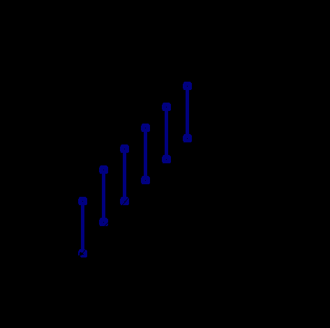
Figure 2: Uniform Linear Array Geometry with Two Incident Signals
In an ideal antenna configuration, the base station antenna should not have significantly more elements than a typical commercial base station antenna. Furthermore, the array geometry should not be a linear array because of front to back ambiguity that does not allow the adaptive algorithm to selectively null out interferers coming from the opposite side of the signal of interest.
An existing antenna array that supports sectored spatial filtering consists of six vertical elements arranged as in Figure 3. While six elements can theoretically null out five interferers, the urban interference scenario as reported in [6] suggested that in a suburban area, such as Tyson's Corner outside of Washington DC there are several multipath components in addition to co-channel interferers. It is therefore advantageous to consider an eight-element array with a similar sectored arrangement. For a crowded urban area, a multi-element array depicted in Figure 3 may be more appropriate to combat multipath and co-channel interference. Each facet of the multi-element array can be arranged as shown for ease of fabrication, installation and maintenance.
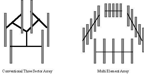
Figure 3: Base Station Antenna Array Geometry
When an MVDR type algorithm is used for beamforming, a difficult problem is the calibration of the antenna array to obtain the steering vectors. The practicality in characterizing the array manifold a(q) does not seem to exist for different array geometries and for a continuous range of q. First, there is no economic advantage in calibrating the antenna array for every wireless base station, which has to be performed due to unavoidable differences between the arrays. Secondly, the direction of arrival of a user signal relative to a base station is usually not known in advance and has to be estimated and updated. This will necessitate the use of a direction finding algorithm that will also depend on the complete knowledge of the array manifold.
An alternative to MVDR beamforming that is gaining acceptance in the array signal processing community is a class of algorithm known as blind adaptive beamforming. In blind beamforming, the knowledge of the array manifold is not required. Instead, other signal properties are used for adaptation such as
An adaptive algorithm controls the beamformer weights such that the system can learn the unknown or time-varying environment and adapt itself. Blind adaptive beamforming algorithms represent the most promising approaches to date. Computationally, they are difficult to implement in terms of efficiency and response time requirements. However, as the speed and price of DSP hardware improve, the technology push in this direction is becoming more aggressive.
Blind Adaptive Beamforming Algorithms
In this section, some of the popular blind adaptive beamforming algorithms are described.
CMA-LMS: As presented in [7], the Constant Modulus Algorithm (CMA) is based on Least Mean Square (LMS) adaptation. Taking advantage of the fact that frequency or phase modulated signals have a constant envelop, an error signal at each k-th iteration step is formed by subtracting the beamformer output magnitude from unity, then recursively updating the weight using the LMS algorithm to descend on the error surface, i.e.,
![]() , (3)
, (3)
![]() , (4)
, (4)
![]() , (5)
, (5)
where sgn(x) is the sign of x. Once convergence is achieved, the signal data is removed from the array data and passed on to the next CMA-LMS stage where the next signal is processed using the same processing scheme. Figure 4 below illustrates the CMA-LMS processor for FM demodulation of two co-channel signals.
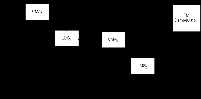 Figure 4: CMA-LMS Processing Block Diagram
A by-product of the CMA-LMS algorithm is a(qi), which is the steering vector of each signal found. When the array calibration data is available, this steering vector can be used for estimation of the signal direction. As the convergence of LMS adaptation is slow, an alternative is to use Recursive Least Square (RLS) which is known to provide faster convergence at the expense of more computational complexity.
MT-LSCMA: Multitarget LSCMA [8] can blindly adapt an antenna array to separate and capture multiple signals by exploiting only the low modulus variation of the communication orthogonal weight vectors, this algorithm adapts in parallel each weight vector using the least squares CMA (LSCMA). A block diagram of MT-LSCMA is shown below in figure 5.
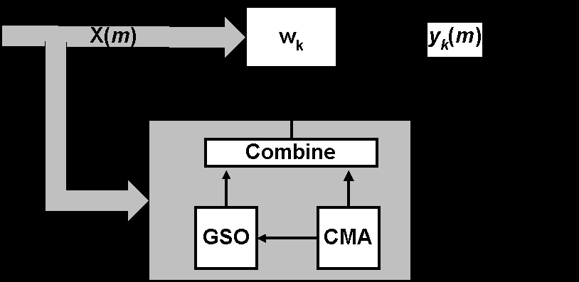
Figure 5: Multitarget LSCMA Block Diagram
The processor structure is a multiport beamformer that forms an M-element vector output signal y(m) = {yk(m), k = 0, ..., M} from the M-element vector input signal x(m) using the beamforming transformation y(m) = Whx(m). The individual beamformer weight {wk, k = 0,..., M} on each output port are adapted using a block-update Least Square CMA,
![]() , (6)
, (6)
where ![]() is a block-update estimate of the correlation matrix computed over N samples, and rk(m) is the constant modulus reference signal on the kth output port computed using,
is a block-update estimate of the correlation matrix computed over N samples, and rk(m) is the constant modulus reference signal on the kth output port computed using,
 , (7)
, (7)
![]() . (8)
. (8)
During the adaptation, a Gram-Schmidt orthogonalization (GSO) of the weight vectors is performed to prevent convergence of the weights to an identical solution. Those weight vectors that have large correlation coefficients with other weight vectors are replaced by the GSO results. When this algorithm converges, it can separate the signals and direct them to different output ports.
Based on simulation results, a plot of the antenna beam pattern for each port of an eight-element antenna array is shown in figure 6. In this figure six users transmit signals from six different directions, which are 40, 80, 120, 160, 200 and 240 degrees from the broadside of the antenna array, respectively. It can be seen that for one specific user on each port, the desired signal is extracted while all the other interference is nulled out.
SCORE: In the Spectral Coherence Restoral algorithm [9], it is assumed that the specific cyclostationarity properties are either known at the receiver or can be estimated. One of these properties can be represented by a cycle frequency a, which for digital frequency can be the baud rate of the signal itself. If it is known that the signal of interest s(n) is cyclostationary with cycle frequency a but the interferer is not, then a reference signal u(n) can be derived directly from the data,
![]()
![]() , (9)
, (9)
where c is any spatial filter weight vector such that ![]() , and the lag time t is chosen to maximize the cyclic autocorrelation function
, and the lag time t is chosen to maximize the cyclic autocorrelation function
![]() . (10)
. (10)
Since s(n) is correlated with u(n) but uncorrelated with the interferer, this leads directly to the least square SCORE (LS-SCORE) optimization problem of the cyclic cross-correlation coefficient,
![]() (11)
(11)
which has the solution for LS-SCORE,
![]() (12)
(12)
In order to choose c so as to minimize convergence time, the joint optimization of Equation (12) for both w and c leads to the Cross-SCORE algorithm and the dominant eigenvector w1 and c1 of the problems
![]() , (7)
, (7)
![]() , (8)
, (8)
where m = 1, ..., M and ![]() . For L multiple signals having the same cycle frequency a, the first L eigenvectors are taken as beamforming weights.
. For L multiple signals having the same cycle frequency a, the first L eigenvectors are taken as beamforming weights.
Having described representative blind adaptive algorithms, the practical issues relating to the use of these algorithms on current cellular standards are presented as follows. In FDMA, each user is assigned a frequency, and thus a narrow band beamformer can be repeatedly updated to track mobile users. For the TDMA system, users share time slots within a frequency channel. The problem arises because users in the same assigned frequency can be geographically diverse, causing the narrow band beamformer to be confused. For this kind of a problem, a decision-directed beamformer can be used for distinguishing the different users in the same TDMA slot. For CDMA, the choice is between a narrow band and broadband beamformer. One can treat the whole bandwidth of interest containing the signal of interests and then capture each one, or each user can be despread before beamforming so that the despread signal is a narrow band signal.
Reciprocity, i.e., the use of the received beam weights to transmit the signal to the mobile, is not straightforward. There is a 45 MHz separation between the forward and the reverse link. Therefore to use the received weights for transmission, the channel has to be reciprocal. The multipath structure might change over a 45 MHz spectrum, and when not properly identified and compensated may cause unintentional interference. This will be a problem for any cellular systems whose forward and the reverse link are separated in frequency.
Processing Architecture
The current generation of commercial wireless product employs readily available DSP technology to digitize the RF spectrum with great fidelity and then perform all of the base station functions using software radio architectures. Most of these functions are performed by executing software on a general purpose DSP board, but the first stage of frequency conversion is performed by specialized decimating down conversion chip, such as the one produced by Harris Semiconductor.
Using the software radio technique [10], a common hardware platform may provide all of the current base station functions and yet retain enough flexibility to meet future requirements through alternative software application programs. The products are configured through a set of hardware and software modules and interconnected using industry standard mechanical, electrical, and software interfaces. These modules may be combined to provide user-configurable equipment suites including complete cellular, PCS, macrocell, and microcell base station and smart antenna applique. Software selectable options may include domestic and international air interface standards, base station controller-to-switch interface, fixed omni-directional, sector or smart antenna, and new service feature such as fraud detection and mobile geolocation.
Taking advantage of this flexible architecture, Figure 7 below depicts a configuration being built by the Mobile and Portable Research Group (MPRG) at Virginia Tech [11] for adaptive array research. The RF front end is essentially the only place where analog is involved. The digitized signal will be decimated and digitally filtered by the DDC at the appropriate rate to accommodate any frequency band of interests. The decimated signal is then fed into the block called Local High Speed Processing, which may include such functions as IF filtering, Doppler processing or despreading before the data processing performed on the Analog Device 21062 or equivalent DSP chip. As the demand for processing load increases with the complexity of the algorithm, more DSP can be added to share the increased burden.
As an example of the software radio architecture, the data processing architecture for the multi-target CMA algorithm can be arranged as shown in Figure 8. Here, each of the M input signals is taken from its RF front end and baseband conversion into the DSP, where the MTCMA algorithm can be executed in parallel or semi-parallel when only a small number of DSPs are available. The other algorithms may be partitioned in a different fashion in order to achieve optimal performance.
Conclusion
The need for increasing re-use of frequencies is of great interest to the cellular telephone industry. When a cellular base station uses the same transmit and receive frequency for several spatially separated mobile units, the frequency’s information capacity is greatly increased. At present, directional antennas that cover a quadrant are used for this purpose; the techniques proposed here should be much more efficient. The uses of blind adaptive beamforming without the need for array calibration, will provide economical base stations with tremendous operational flexibility.
References
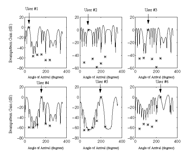
Figure 6: Beam Patterns for LSCMA
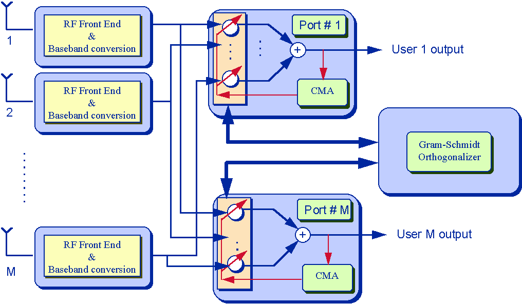
Figure 7: Software Radio Architecture for Array Processing

Figure 8: Multi-Target CMA on Software Radio Architecture