VACETS Technical International Conference (VTIC97), San Jose, July 1997
Stereo-Vision-Based Robot Control Without Calibration
Minh-Chinh Nguyen
Institute of Measurement Science
Federal Armed Force University Munich
85577 Neubiberg - Germany
Tel.: +49 89 6004-2127; -2625
Fax.: +49 89 6004 3074
E-mail: [email protected]
Abstract:
A novel concept of "object- and behavior- based stereo vision" for vision-based robot control, which enables a robot manipulator to handle an object, is introduced . It eliminates the need for a calibration of the robot and of the visual system, and comprises an automatic adaption to changing parameters. It uses no real-world coordinates, but all effects of control signals of a robot are based on stereo visual observation, which allows a direct transition from image coordinates to motion control commands of a robot. By this approach, the abstract coordinate transformations have been avoided, instead, image data are used directly to control the behavior of the robot, or the interactions of the robot with physical objects.
Keywords: Object-and behaviors-based stereo vision; Vision-based robot; Stereo-vision based robot control;
1. Introduction
Making robots capable of working in unstructured or weakly structured environments implies providing them with sensors and certain reasoning capabilities in order to allow them to understand the surrounding environment. A large class of tasks in such a context is the manipulation of objects. Up to now, the dominating approach is to use databases to store a priori knowledge about all objects admitted in the scene, this information is then used to recognize objects in the scene, to determine possible grasping points which enables the manipulation of possible predefined grasping instructions. This partly explains why several systems have been reported in recent years which try to deal with this problem, however, most of them use generic object models like "cylinder" or "box" which do not need to align the end effector to coincide with the orientation of the object, and thus limit the allowable objects to instances of generic models supported by the system, implying some sort of a priori knowledge about the objects to be handled. In addition, vision-based control of a manipulator typically requires a careful calibration of the optical subsystem, including the cameras and the lighting, and of the mechanical subsystem. Such a system tends to be rather cumbersome and expensive. Moreover, because neither subsystem is perfectly stable the calibration has to be repeated after relatively short time intervals, and also after any maintenance.
A robot not requiring any calibration of its subsystems and having ability of vision and self-learning, in the way of adapting to situations and handling flexibility in various environments, situations and objects, would be of great practical advantage. Applied uses of such a robot could be various. For example, it could be used in transport in an unknown environment in a building and outdoors without special infrastructure, and in the manipulation of objects of unknown shapes, sizes and orientation or clearing of objects from floors, working surfaces, conveyor belts etc. It is evident that techniques for an object manipulation without the use of object models as well as position of object can be useful in many application areas. An approach to the realization of such a robot is presented below. It utilizes a close interaction between image interpretation and motion control as well as aligning the end effector to coincide with the orientation of the object to perform a continuous implicit calibration during normal operation. This self-calibration is automatically limited to those parameters which are actually necessary for motion and alignment control.
The continuous updating of the internal knowledge of system parameters may be considered a form of learning. It also adapts the control to changes of characteristics of the robot e.g. mechanical wear or replacement of parts, of the sensors e.g. camera mounting or focal length of the camera lens, and of the environment e.g. positions, orientations of objects to be manipulated, or lighting.
To avoid the necessity of calibration for robots Cooperstock and Milios (1993) have used neural networks to represent the functions necessary for controlling a manipulator that was mounted on a movable platform. However, neural networks require an lengthy training phase before they can begin to do useful work, and it is difficult to design neural networks that can continue to learn, and relearn, while they perform their duty after the initial training phase [2]. Graefe and Ta (1995) has proposed different methods of object- and behavior-oriented stereo vision allowing a direct transition from image coordinates to motion control commands of a robot. However, this approach handles only cylindrical objects which have a vertical axis of symmetry and can be grasped without knowledge of the gripper orientation with respect to the object orientation [4]. With a newer version of the algorithm Vollmann and Nguyen (1996) proposed the new method that is possible to manipulate a ballpoint pen without restricting its orientation [11]. However, to grasp an arbitrary shape in an arbitrary orientation would require an arm with at least six degrees of freedom, Moreover, recognizing suitable point for grasping such objects and a suitable reference point is difficult. Yet, a special solution is presented below which allows to carry out with a five degree of freedom articulated arm.
2. Experimental setup
2.1. System overview
A specific setup has been used for developing and testing our approach to vision-based robot control in real-word experiments.
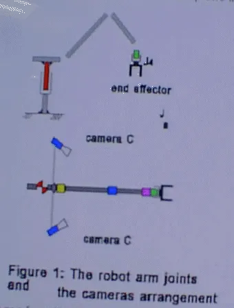
A 5 degree of freedom articulated arm (Mitsubishi Move master RV-M2) is used for picking up objects. Of the 5 degrees of freedom, one (J4) refers to the rotation of the gripper around its axis. The remaining 4 degrees of freedom correspond to the joints J0. . . .J3 (cf. Figure 1). Joints J1 . . . J3 allow the gripper to be moved within a certain section of a vertical plane, the work plane. Joint J0 allows the arm to be rotated around a vertical axis, thus determining the azimuth of the robot's work plane. In our experiments joint J3 was always controlled in such a way that the gripper was in a vertical orientation, as indicated in Figure 1. Our arm has thus four independent degrees of freedom remaining, corresponding to joints J0, J1, J2 and J4.
Two video cameras are mounted on the arm and participate in the rotation of the arm around its vertical axis, but they aer relative to the work plane of the robot. The cameras are mounted on opposite sides of the work plane. The location and orientation of each camera are somewhat arbitrary and not exactly known, but each camera should be mounted in such a way that its field of view covers that area within the work plane in which objects are to be manipulated, as in Figure 1.
The images from the two cameras are processed, then motion control commands are issued to the robot. Both of these actions are carried out by an object-oriented vision system based on two frame grabbers, each contain a TMS320C40 Digital Signal Processor, and each of them is connected with one of the cameras.
The control of the robot is based entirely on an interpretation of the images of two cameras. Uncontrolled ambient light is used for illuminating the scene. The task to be executed by the robot is to find a single object that may be located anywhere and in any orientation in the robot's 3-D work space, to reach to the object, then to align the end effector relative to orientation of the object, and, finally, to pick it up from above by a two-fingered parallel gripper of 2 cm wide and 2,5 cm height.
2.2 Requirements
In sharp contrast to the classical approach, our approach requires no knowledge regarding the exact locations of the cameras (except that they should be located some distance away from the work plane of the robot opposite of one another) the exact viewing directions and internal parameters of the cameras (except that both cameras should have the actual work space of the robot in their fields of view)
3. Object- and Behavior-Based stereo Vision
3.1. State of the object and Grasping position
As already above mentioned that our robot have only 5 degree of freedom, so that in order to grasp the object in any arbitrary position successful without any collisions, then the grasp can be carried out only and only from above, i. e., it should be automatically determined a "sensible" grasping position according to a state of the object.
Our experiments joint J3 (Figure 1) was always controlled in such a way that the gripper was in a vertical orientation, this character should be used to determined the state of the object (lying or standing object). In the case of standing object, the grasping position should be on the top of the object, (the direction toward the gripper), and its height should be smaller than the height of the gripper to avoid collisions between the gripper and the object.
To determine the state of the object, the "good" grasp position should be first determined. For the case of a two-finger paralleled gripper this means that we have to find at least one suitable position on the surface, although our approach is not based on object model, but we allow all pairs of parallel or fast parallel edges to be candidate grasping positions, i. e., all combinations of two parallel or almost parallel edges form a possible grasping configuration. Exclude from the quality measure is the "good" grasp position which would be the pair of longest parallel or almost parallel edges in the images, e.g. position Nr.1 (Figure 2). After the "good" grasping configuration is found, in the images its orientation, i.e., the slope of edge ORE1-ORE2 and edge OLE1-OLE2 will be compared with the vertical orientation of the gripper, i. e., the slope of edge GVE1 -GVE1 of the gripper (Figure 2). If, and only if, two these orientations coincide or almost coincide in both the left image and the right image, then it can be sad that the object is in a standing state. In this case, the "good" grasp position is not the sensible grasp position, and the sensible grasp position should come from above the object, e.g. position Nr.2 (Figure 2). In other case, the sensible grasp position is the same good grasp position.
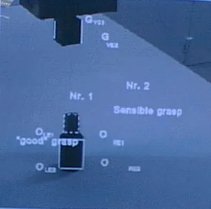
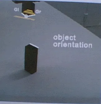
Figure 2: The grasping position with a standing object Figure 3: The standing object orientation
3.2. Relative orientation of the object and of the gripper
The orientation of the object in the images is defined as the orientation of the sensible grasp position. In the case of lying object, it is evident that the object orientation can be determined through the slope of the parallel or almost parallel edge pair. However, in the case of the standing object, the object orientation is determined through slope of the longest edge at the sensible position (the highlighted line in the Figure 3). But when the long of these edges are no or slight difference, then arbitrary one of the edges is chosen. However, when both of edges are very short, then the determine of their slope will meet a big error or impossible. In this case the grasp can be carried out without need of rotating the gripper.
The orientation of the gripper in the images is determined relatively through the lope of the surface boundaries, e. g. the highlighted lines Gl-G and Gr-G in the figure 3. (For more details cf. [Vollman, Nguyen 1996].
3.3. Rotation around the vertical axis
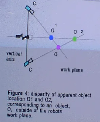
To be able to be picked up, an object must be located in the work plane of the robot. Now let us assume that the object is not located in the work plane (Figure 4).To make the work plane coincide with the object, the joint angle a0, corresponding to joint J0, must be modified until the two set of the motion control words based on the image of the left camera and the right camera are identical. Figure 4 shows why the two results will be different if the object is not located in the work plane. The distance between the object, O, and the camera cannot be determined directly. Rather, in the rendezvous procedure it is implicit that any object seen is located in the robot's work plane. Controlling the joints, J1 and J2, based on the image of camera C1 would, therefore, generate a motion of the gripper towards O1, the projection of the object O onto the work plane as seen by C1. Similar, basing the motion control on the image of camera C2 will cause a motion of the gripper towards O2. The two sets of motion control words will be identical if, and if only O is located in the work plane, because only then will O1, O2 , and O be at the same location. Therefore, if the two set of control words computed on the basis of the two images are different it may be concluded that the object is not located in the work plane. In this case, the control word for joint J0 should be modified, causing the azimuth angle, a0, of the work plane to change. The correct sign and magnitude of Dw0, the increment of the corresponding control word which makes the work plane coincide with the object, would be determined basing on the disparity of the two sets of control words, Wa and Wb, computed from the images of the two cameras.
3.4. Motion within the Work Plane
Up to this point it has been assumed that the object was located in the work plane, in other words, the robot's work plane already coincides with the object. To reach the object it is sufficient to make the image of the gripper coincide with the image of the object. The task is then to make the image of the gripper coincide with the image of the object to be grasped. The key idea is here that we are not at all concerned with distances, coordinates, or any other relations in the real word, but only with the image of either one of the camera for accomplishing this goal, and it did not matter which one of them was actually used. The images of the object and of the gripper coincide if, and only if, the object and the gripper are at the same location. To do this we need not be concerned with any coordinate system defined by the external world. We may, in effect, use instead a non-Cartesian system defined by the joint angles a1 and a2 in the work plane. Even better, we may use a coordinate system defined by the control words, wa and wb, that correspond in a specific, but initially unknown way to the joint angles. The task is then reduced to the question which increments, Dwa and Dwb, must be added to the present control words, wa and wb, to make the image of the gripper coincide with the image of the object.
3.5. Rotation of the end effector
When the image of the gripper near enough the object reference point, i.e. the distance between the gripper and the object is just right for the gripper to pick the object up, although in the images the gripper is still distinguishable from the object, then J0, J1, J2 and J3 should be fixed. Only J4 refers to the rotation of the gripper around its vertical axis to align the orientation of the gripper relative to the orientation of the object. It is clear that with an orientation of the object, to align the orientation of the gripper relative to the orientation of the object, two possible control words exist which make the orientation of the gripper meet the orientation of the object. But, for reasons of efficiency, the desired solution requires a small change in this joint angle, i. e. the gripper will be rotated to left or to right. At one moment, only one of the two cameras was necessary, and it did not matter which one of them was actually used. Their images, and the object and gripper orientation, are different, but the control word increments computed in the aligning procedure are the same, regardless of the camera whose image is used. The reason is that there is only one correct motion and, thus, only one correct set of control word increments. However, in order to reach the goal simply and conveniently, depends on the orientation of the object in the images, the image and the edge of the gripper boundaries in the chosen image should be used first in such a way as to minimize the amount of changing images in aligning process. That means depending on the orientation of the object in the images that one to two images, i. e. one to four edges of the end effector boundaries will be alternately used until the gripper orientation coincides with the object orientation.
The task is then now to motion the gripper (J1, J2) as described above within the work plane until the image of the gripper coincides with the image of the object. Then suffices only to open the gripper and then close it to grasp the object.
4. Experimental Results
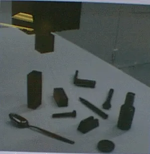
We have run numerous tests on some different objects, among them those displayed in Figure 5.
The object was placed on a support of unknown height (0 to about 10 cm) somewhere and in arbitrary orientation on a table where it could be reached by the robot arm.
In the experiments, the object was located and grasped reliably, regardless of its initial location and orientation in the work space of the robot.
The adaptability of the system was tested by moving one of the cameras or both of them by an arbitrary amount in a way unknown to the system. As expected, the grasping operation could immediately continue without any recalibration whatsoever.
The results are still reliable, even if the viewing direction of the Figure 5: the objects were used in cameras are changed during process of the gripper reaches the
experiment object, or while aligning the orientation of the end effector relative to the orientation of the object (due to using the relative coordinates in the images).
5. Summary and conclusion
Robot vision without calibration is possible. A method of "stereo-vision-based" for robot vision control which enables a robot manipulator to handle an objects without a priori knowledge of the object. It does not require the robot, or the vision system, to be calibrated, and it provides an automatic adaption to changing system parameters. The key point of the method is a direct transition from image data to motion control commands. This direct transition avoids not only cumbersome computations of coordinate transformations and inverse kinematics, but it also makes it unnecessary to know numerous system parameters that would otherwise have to be determined by expensive calibration procedures.
The validity of the concept has been demonstrated in real-world experiments where an articulated arm robot grasped objects that were located at arbitrary positions and orientation in 3-D space.
Grasping objects of arbitrary shape in arbitrary orientation with the arm of six degree of freedom is still going on.
References
[1] Brost, Randy C.: "Automatic Grasp Planning in the Presence of Uncertainty". The Int. Journal of Robotics Research, Vol. 7/1, pp 3-17, 1988.
[2] Cooperstock, J. R.; Milios, E. E.: "Self-supervised learning for docking and target reaching". Robotics and Autonomous Systems 11, pp 243-260, 1993.
[3] Graefe, V.: "Dynamic Vision Systems for Autonomous Mobile Robots". Proc. IEEE/RSJ International Workshop on Intelligent Robots and Systems, IROS '89. Tsukuba, pp 12-23, 1989.
[4] Graefe, V.; Ta, Q-H :"An Approach to self-learning Manipulator Control Based on Vision". Proc. International Symposium on Measurement and Control in Robotics, pp 409-414, Smolenice, 1995.
[5] Hollinghurst, N.; Cipolla, R.: "Uncalibrated stereo hand-eye coordination". Image and Vision Computing, Vol. 12/3, pp 187-192, 1994.
[6] Jain, A.K and Flynn, P.J., editor. "Three-dimensional Object Recognition Systems". Advances in image communication 1. Elsevier, 1993.
[7] Kamon, I.; Flash, T.; Edelman, S.: "Learning to Grasp Using Visual Information". Proc. IEEE International conference on Robotics and Automation, vol. 2, pp 2470-2476, April 1996.
[8] Nguyen, M.-C.; Graefe, V.: "Object Manipulation Controlled by Uncalibrated Stereo Vision". The Second Chinese Congress on Intelligent Control and Intelligent Automation; Xian-China, June, 1997.
[9] Rutishauser, M.: " From Triangular Meshes to Grasps: A 3D Robot Vision System Handling Unmodeled objects". Ph.D. thesis, Hartung-Gorre, 1995.
[10] Stanstield, S. A.: "Robot Grasping of Unknown Objects: A Knowledge-based Approach". The Int. Journal of Robotics Research, Vol. 10/4, pp 314-326, 1991.
[11] Vollmann, K.; Nguyen, M.-C.: "Manipulator Control by Calibration-Free Stereo Vision". Intelligent Robots and Computer Vision XV, Proceeding of the SPIE, Vol. 2904. Boston, USA, pp. 218-216
[12] Yoshimi, B. H.; Allen, P. K: "Active, uncalibrated visual servoing". IEEE International conference on Robotics and Automation, Volume 4, pp 156-161, San Diego, CA, 1994.