MAGNETOMECHANICAL PROPERTIES IN FINEMET TYPE ALLOY
H. Duonga, L. Malkinskib and R. Grössingera
a) Insttitut für Experimental Physik, Technische Universität Wien
Wiedner Hauptstrasse 8-10/131, A-1040, Wien, AUSTRIA
b) Institute of Physics, Polish Academy of Sciences
Al. Lotnikow 32/46, PL-02-668 Warszawa, POLAND
Amorphous ribbons of the compositions Fe76.5-xCu1NbxSi13.5B9 (x =2, 3, 5) were used for studying the field dependence of Youngs modulus (D E effect) at room temperature. In order to vary the amount of the nanocrystalline phase the heat treatment was performed at a temperature range of 330°-500°C for different annealing time periods. Additionally a transverse field was applied. The sample with a Nb concentration x = 2 annealed at 400°C for 6 hours in a transverse field exhibited the best magnetoelastic parameters: a minimal D E effect and a magnetomechanical coupling coefficient k close to 75%. In addition domain observations using the Kerr effect were also performed. The transversal field annealing process leads to stripped type domain pattern which explains the achieved magnetoelastic results.
Introduction
A new type of nanocrystalline material has filled up the gap of soft magnetic materials lying between the amorphous and microcrystalline materials. Applying a proper annealing procedure, a precursor amorphous ribbon based on iron transforms into a two phase structure material which contains nanosized crystal grains randomly distributed in the remaining amorphous matrix [1]. A superposition of the two contributions to the magnetostriction from the nanocrystals and the amorphous phase leading to a low l S value and an averaging process of the effective anisotropy due to a gain size smaller than the exchange length causes a significant decrease of these parameters. Consequently, samples with excellent soft magnetic properties, very low coercivity and very high permeability were created.
In this work the Youngs modulus as a function of annealing temperature as well as the applied field were investigated. The obtained results were analyzed in order to achieve the optimum annealing process in order to get the best piezomagnetic parameters.
Experiments
As-quenched ribbons Fe76.5-xCu1NbxSi13.5B9 (x =2, 3, 5) were supplied by Vacuumschmelze VAC (Hanau). Their width and thickness are 15 cm and about 20 µm, respectively. Samples used in our experiments were cut into strips with a length of 8 cm and a width of approximately 0.5 cm. For avoiding the external stresses which are induced by cutting, a method using the thin sharp wire and powder was applied. The density of the samples were measured by the Archimedes method using a Ni reference with an error less than 1% [2]. A heat treatment at temperatures from 330° to 400°C for different times applying a transverse field was carried out to produce materials with different induced anisotropies. To prevent oxidation all annealing processes were performed in vacuum of ~ 10-4 Torr. The D E(H) effect of both as-cast and heat treated samples were studied at room temperature using the resonace-antiresonance (ultrasonic) method [3]. For the sake of comparison the vibrating reed method was also used to confirm the gained results [4]. From these dependencies, the sound velocity and also the magnetomechanical coupling coefficient can be determined. Additionally, the microstructure was investigated using a computerized magneto-optic Kerr technique. The arrangements of the measuring system was described in more detail elsewhere [5]. These domain observations were performed in the demagnetization and in the remanence state at room temperature.
Results and discussion
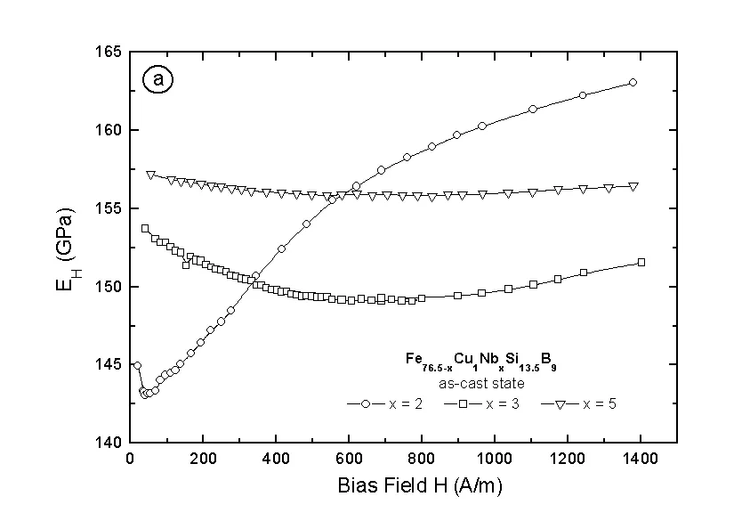
Fig.1(a) and 1(b) present the Youngs modulus as a function of the magnetic field for the as-received amorphous ribbons measured by the ultrasonic and the vibrating reed method, respectively. We can see the frequency dependence of the pick-up signals correspond to a certain external field shown in Fig. 1(b). Collecting the maximas of this curve, the field dependence of the D E effect can be revealed which is, in this case, plotted as a dotted line.
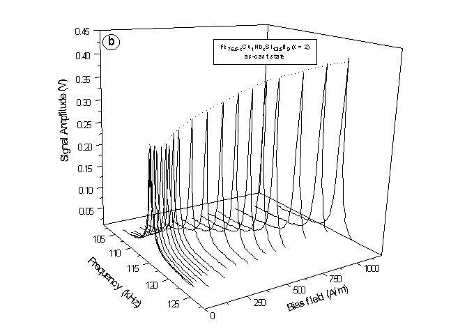
Fig. 1 The Youngs modulus as a function of the magnetic field for as-cast
Fe76.5-xCu1NbxSi13.5B9 measured by the a) ultrasonic method and b) vibrating method.
In general, the E(H) curves are very typical for the metallic glass materials. The difference between the initial and the minimal value is not always distinguishable. For the sample with x = 5, the minimum of Youngs modulus is even not found in the measured field range. Taking into account that the D E effect is reverse proportion to the effective magnetostriction l S and considering that the substitution of niobium in the FINEMET alloys leads to a reduction of the magnetostriction for as-cast materials [6], the decrease of magnetoelastic property with increasing Nb concentration is understandable. This becomes more clear plotting the magnetomechanical coupling coefficient k as a function of the magnetic field as shown in Fig. 2(b). Though the maximum k values are equal or even better than that of ferrites, permaloy or that of many other polycrystalline piezomagnetic materials, the k-results do not exceed 30%. Fig. 2(a) shows the field dependence of the sound velocity which behaves similar as the Youngs modulus.
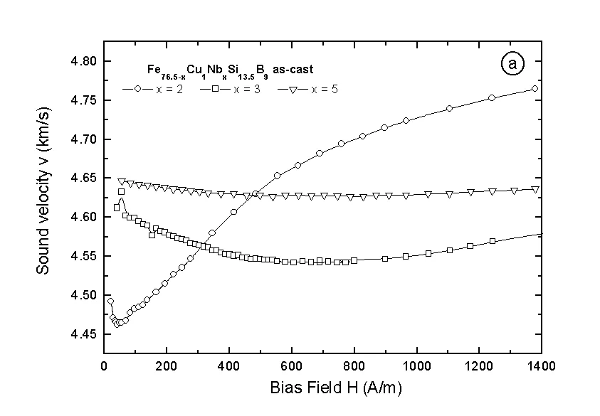
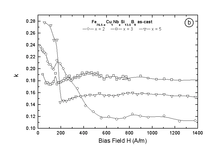
Fig. 2. The field dependence of: a) the sound velocity and b) the magnetomechanical coupling coefficient k for Fe76.5-xCu1NbxSi13.5B9 in as-cast state
Because the D E-effect is mainly determined by the domain structure, for the low magnetoelastic parameters of the as-cast materials an unfavorable domain state may be responsible. Fig. 3 shows the domain pattern for the as-received amorphous material which exhibits large domains parallel to the ribbon axis. The magnetization process thus is mainly dominated by domain wall movements. This causes almost no contribution to the magnetoelastic effect.
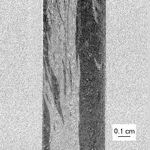
Fig. 3 Domain pattern of as-cast amorphous Fe76.5-xCu1NbxSi13.5B9 (x = 2)
The occurrence of many smaller not aligned domains at the left side of the sample is probably due to local stress centers caused by the cutting process.
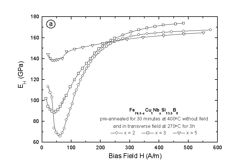
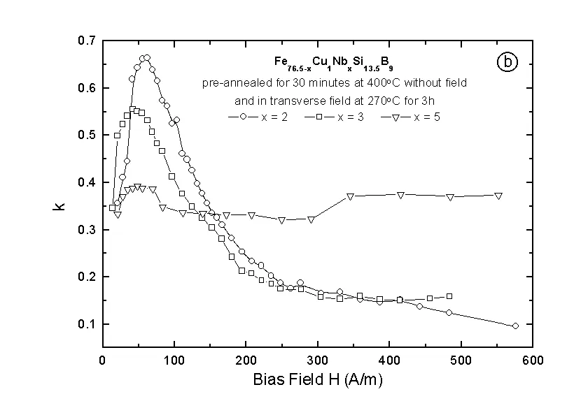
Fig. 4. The field dependence of: a) the Youngs modulus and b) the magnetomechanical
coupling coefficient for the Fe76.5-xCu1NbxSi13.5B9 pre-annealed at 400°C for 30 min.
without field and in transverse field for 3h
In order to get better magnetoelastic properties the samples were then heat treated at different conditions. The first annealing process was devided into two stages: first the samples were pre-annealed at 400°C which is below the crystallization point of all considered FINEMET compositions for half an hour. The aim of this procedure is that the internal stresses created during the quenching process can be removed because of the so-called relaxation phenomenon. The following step is a heat treatment under transverse field. After this heat treatment the magetomechanical parameters were improved significantly, especially for the sample with a Nb concentration of x = 2 as can be seen in Fig. 4(a) and 4(b). A deep minimum in the D E(H) curve and a shift of this minimum to higher field as well as a larger k factor reaching a value of 67% give a hint to a successful heat treatment causing an induced anisotropy. This was enlightened by the domain structure observation presented in Fig. 5a. Strip type domains aligned in the field direction were found. The evolution of these domains starts at outer boundary of the ribbon penetrating to the center. It is a consequence of transverse domain nucleations which always occur at the edges of the as-cast sample [7]. It can be seen, nevertheless, that the annealing temperature and the time period were not really the optimum since there exists still wide domains parallel to the ribbon axis which are located at the middle of sample. This assumption is proved by increasing the annealing temperature to 360°C and also prolonging the time to 6h (see Fig. 5(b)). The longitudinal domains were replaced by wider ones which are perpendicular to the ribbon axis. The domain structure becomes almost perfect in the case of a heat treatment performed at 400°C for 6h which shows a domain patterns parallel to the applied transversal field as shown in Fig. 6.
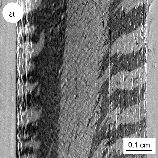
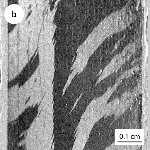
Fig. 5 Domain pattern for Fe76.5-xCu1NbxSi13.5B9 (x = 2) annealed in a transverse field at
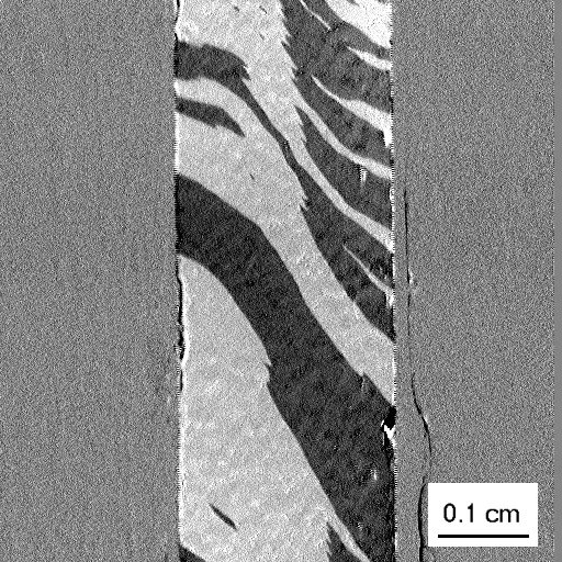
Fig. 6. Domain pattern for Fe76.5-xCu1NbxSi13.5B9 (x = 2) annealed at 400°C for 6h in a transverse field
The absence of an ideal alignment perpendicular to the ribbon axis (because of the effect of the demagnetizing field) can be due to the limitation of the magnetic field intensity of about 10 kA/m which may be not sufficient for aligning all domains parallel to the field direction.
Fig. 7(a) and 7(b) show as a summary the field dependence of the D E effect as well as of the coupling coefficient k. The best result was obtained for the sample with 2 at% of Nb annealed at 400°C for 6h where k reaches a value of 75%. This result is comparable with the best ones achieved on similar alloys in other research laboratories [8].
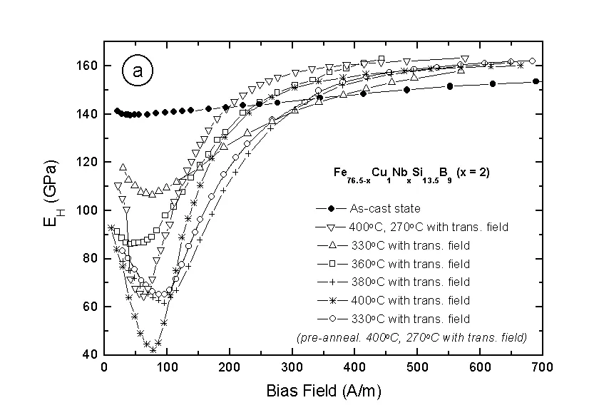
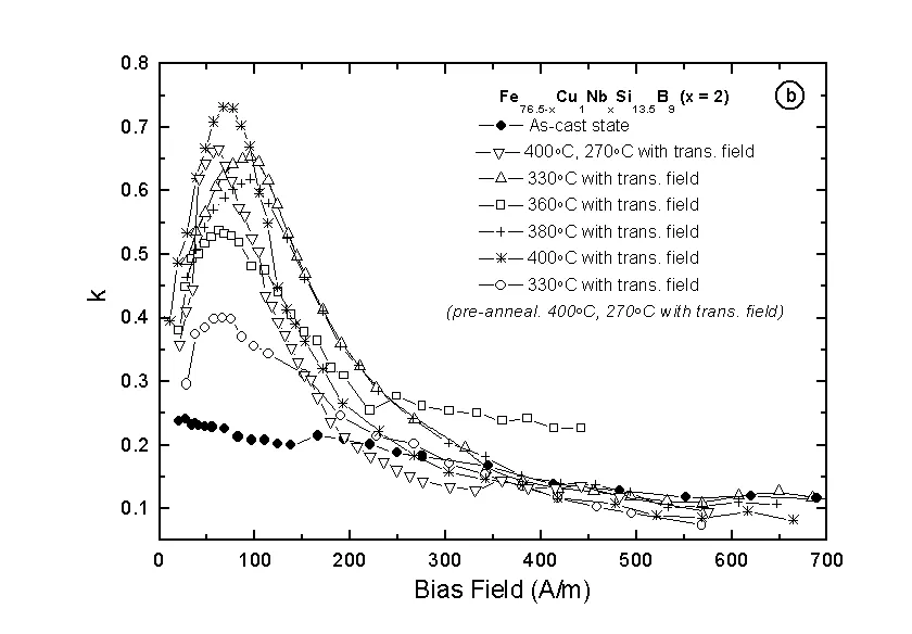
Fig. 7. The field dependence of a) D E effect and b) magnetomechanical coupling coefficient k
for Fe76.5-xCu1NbxSi13.5B9 annealed at different temperatures under a transverse field
Conclusion
The experimental data show that in FINEMET type alloys the magnetoelastic phenomena have a close relation to the domain structure. The 180° longitudinal domain patterns contribute almost zero to the D E effect. The domain wall movement in the magnetization processes do not contribute significantly to the D E effect. Contrary, materials where the magnetization process is determined mainly by a rotation of domain wall - as in the case of transversal field annealed samples - show the best piezomagnetic parameters.
Acknowledgment
The authors would like to thank Mr. Kuzminski for his enthusiastic assistances in the domain structure observations. The density data supplied by Dr. Varga are appreciated as well. This work was supported by the Austrian-Polish Scientific Exchange Program No 19 and KELAG.
References
[8] L. Malkinski, Ph.D. thesis, IFPAN, Warszawa, Poland, 1991.